

Electronic Unit Specification
1. The electronic unit is a dual voltage device. This means that the same unit can be used in both 12V and 24V power supply systems, maximum voltage is 17V for a 12V system and 31.5V for a 24V system.
Maximum ambient temperature is 60C. The electronic unit has a built-in thermal protection which is actuated and stops compressor operation if the electronic unit temperature gets too high.
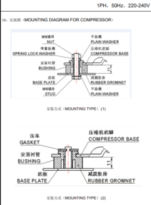
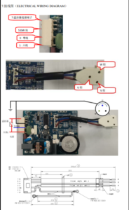
2. Installation (Fig.1)
Connect the terminal plug from the electronic unit to the compressor terminal. Mount the electronic unit on the compressor by snapping the cover over the screw head(1).
3. Power supply (Fig. 1)
a. The electronic unit must always be connected directly to the battery poles(2), connect the plus to (+) and the minus to (-), otherwise the electronic unit will not work. The electronic unit is protected against reverse battery connection.
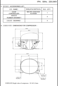
b. For protection of the installation, a fuse (3) must be mounted in the (+) cable as close to the battery as possible. 15A fuse for 12V and 7.5A fuse for 24V circuits are recommended for model QDZH25G, QDZH30G and QDZH35G; 30A fuse for 12V and 15A fuse for 24V circuits for model ODZH65G
c.If a main switch (4) is used, model ODZH25G, QDZH30G and QDZH35G should be rated to a current of min. 20A; model QDZH65G should be rated to a current of 40A @ 12V and 20V @ 24V.
d. The wire dimensions in Table. 2 must be observed. Avoid extra junctions in the power supply system to prevent voltage drop from affecting the battery protection setting.
4. Battery protection (Fig.1)
a. The compressor is stopped and re-started again according to the decided voltage limits measured on the (+) and (-) terminals of the electronic unit.
b.The standard settings for 12V and 24V power supply systems appear from Table.3. Other setting (Table.1) are optional if a connection which includes a resistor (9) is established between terminals C and
5. Thermostat switch(Fig. 1)
a. The thermostat (7) is connected between the terminals C and T. Without any resistor in the control circuit, the compressor with electronic unit will run with a fixed speed of 2000pm when the thermostat is switched on.
b.Other fixed compressor speeds in the range between 2000 and 3500pm can be obtained when a resistor (8) us installed to adjust the voltage (V) of the control circuit. Resistor values for various motor speeds appear from Table.4.
6.Fan (Optional, Fig. 1)
a.A fan (5) can be connected between the therminals (+) and (F). Connect the plus to (+) and the minus to (F). Since the output voltage between the terminals (+) and (F) is always regulated to 12V, a 12V fan must be used for 12V and 24V power supply systems.
b. The fan output can supply a continous current of 0.5A. A higher current draw is allowed for 2 seconds during start.
7.LED(Optional, Fig. 1)
a.A 10mA light emitting diode (LED)(6) can be connected between the terminals (+) and (D). b.In case the electronic unit records an operational error, the diods will flash a number of times. The number of flashes depends on what kind of operational error was recorded. Each flash will last 1/5 second.
After the actual number of flashes there will be a delay with no flashes, so that the sequence for each error recording is repeated every 3 minutes.
There are no reviews yet.